Mythical Lucca Labyrinths

San Martino Cathedral & Labyrinth

Labyrinth carved on a pillar of the portico of Lucca Cathedral, Tuscany, Italy. The Latin inscription says “HIC QUEM CRETICUS EDIT. DAEDALUS EST LABERINTHUS . DE QUO NULLUS VADERE . QUIVIT QUI FUIT INTUS . NI THESEUS GRATIS ADRIANE . STAMINE JUTUS”, i.e. “This is the labyrinth built by Dedalus of Crete; all who entered therein were lost, save Theseus, thanks to Ariadne’s thread.”

Photos and quote by: Myrabella / Wikimedia Commons, CC BY-SA 3.0

For years I thought of labyrinths as simple objects. If one followed the path, the designer presented no choices. Eventually, one would exit or die in the mouth of a monster. The outcome was not your choice but the intention of the designer of the labyrinth.

Then in the fall of 2018, my attitude changed. While visiting Lucca, I had a wild thought. I would create mythical labyrinths of Lucca. They would be of the same species but different individuals.

What is the genome of the Lucca labyrinth? I had no idea. How would I design mythical descendants? Again, I had no idea. However, I did know how to start the design of a computer program. First, I needed a vocabulary to describe the program. Graph theory, a branch of mathematics that describes things (called vertices or nodes) and their relationships (called edges or links), provided that vocabulary. The following figure is a simple graph.

Figure By::AzaToth , Public Domain, Commons Wikimedia

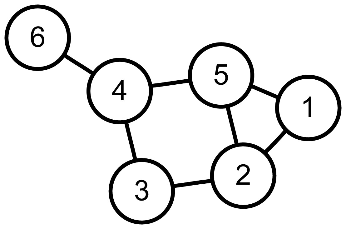
If node one is a labyrinth entrance and node six the exit. Then "walking" 1-5-4-6 is one of many paths. However, for my mythical labyrinths, I need a Hamilton path. Hamilton paths are the result of self-avoiding walks that visit all nodes. For this graph, 1-5-2-3-4-6 is a Hamilton path.

My design uses a graph that maps each location (the nodes) to neighboring nodes (using edges). The program then iterates randomly over Hamilton paths through the nodes. It halts when it finds a mythical Lucca labyrinth.

I plan two more posts about this work.

  • The next will describe the method of iterating over possible paths.

  • The final post will describe the halting condition. That is the definition of mythical Lucca labyrinths.

The remainder of this post addresses the graph design and its relationship with the drawing of the labyrinth.

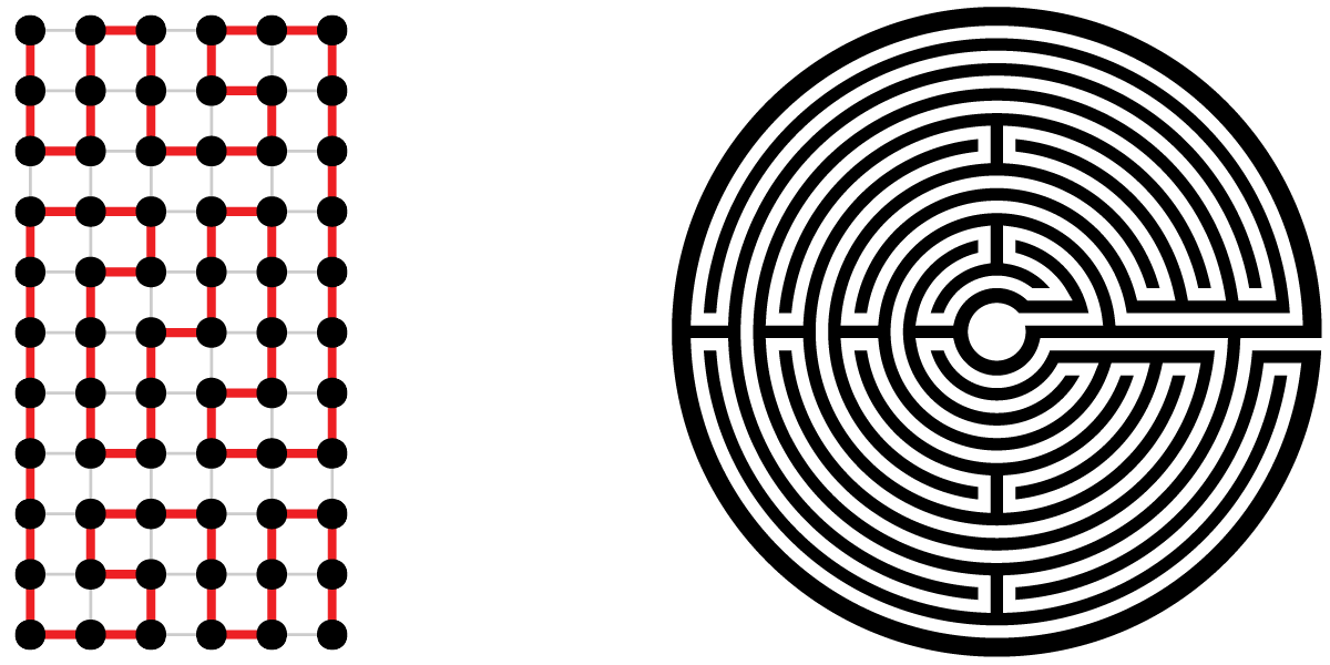
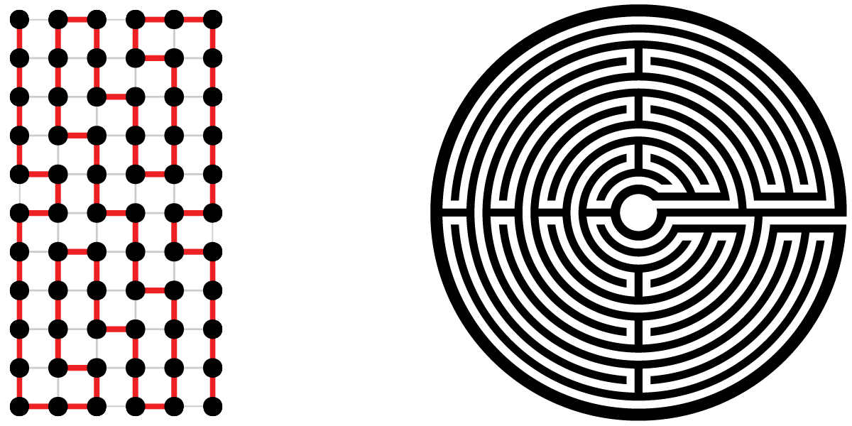
Returning from Lucca, I printed an drawing of the labyrinth. Taking a red magic marker, I attempted to discover the form of a graph and its path, which could describe both the Lucca labyrinth and its mythical siblings. The first and unmistakable set of nodes follows.

The resultant graph and path, in red, follow.

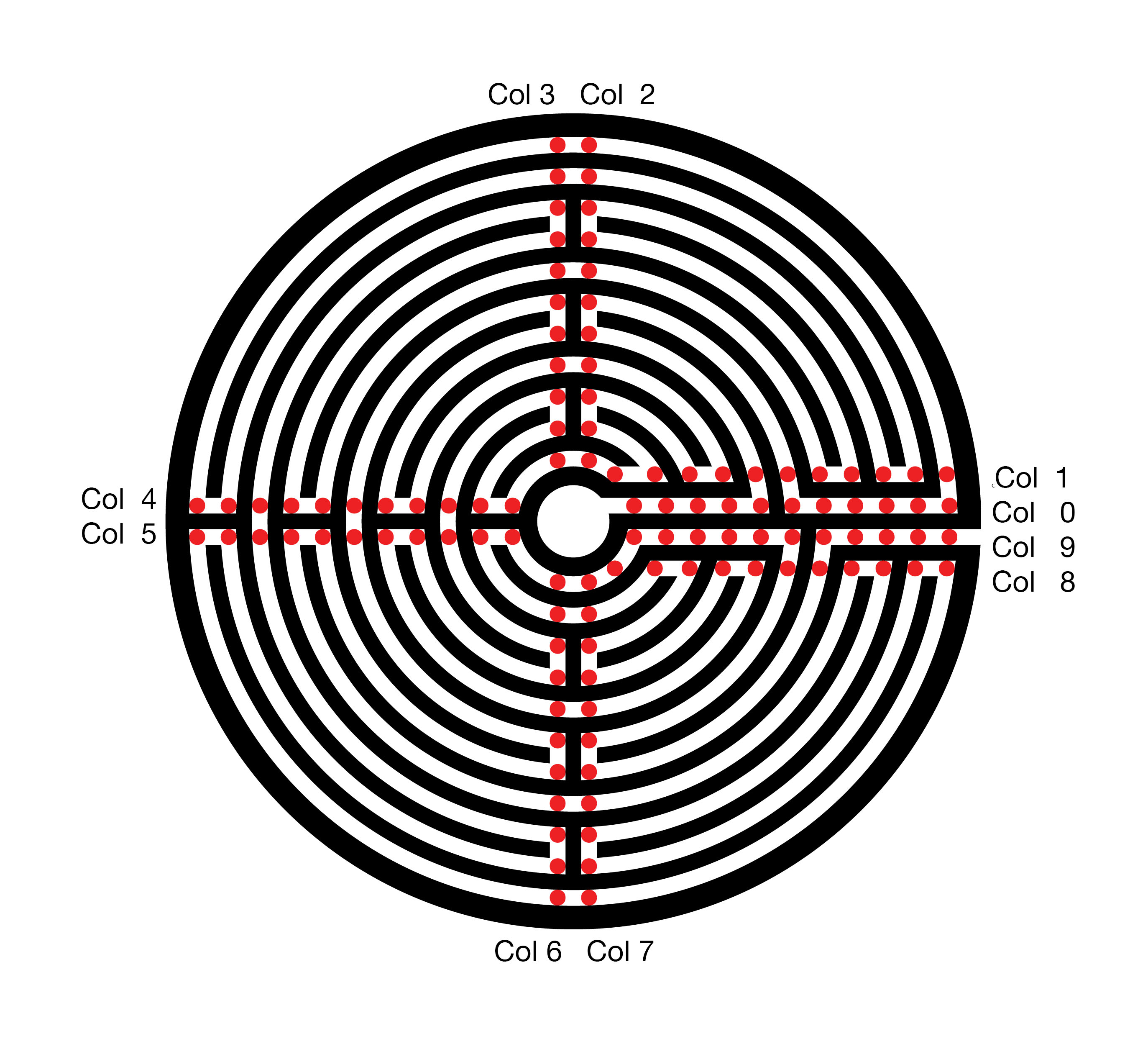
The top row of the graph, row 0, describes the central ring of the labyrinth. The bottom row, 10, maps the outer ring of the labyrinth. The exit from the labyrinth’s central court, column 0, is to the left and the path to the exterior is to the right. The red Hamilton path describes the route of the labyrinth.


This eleven by ten rectangular graph might satisfy my needs. However, it has a fatal flaw. In every row, the path connects the odd columns 1, 3, … 11 to the even column to their right. My mythical labyrinths will also require these connections. Without all of these connections, some of the sweeping arcs will be missing. These arcs are a chief feature of the Lucca labyrinth and, therefore, also required for my myths. Using this Graph, the search space for my mythical labyrinths is very substantial. The program run time will be significantly increased, probably beyond my lifespan and that of my computer.

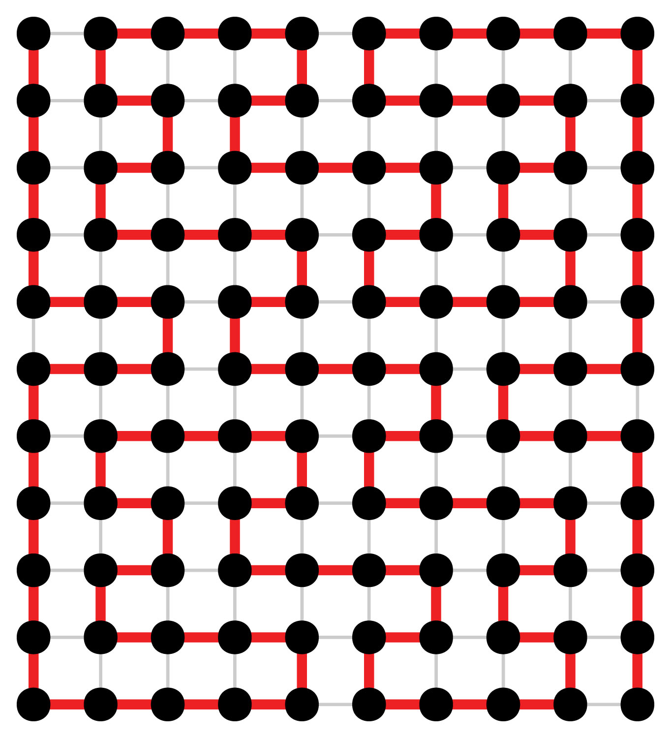
Replacing each pair of nodes, which will always be connected, with a single node avoids checking 44 edges to ensure their presence. However, the new graph does not contain information on every turn. The labyrinth drawing software must cover this missing information. The following analogy illustrates my design. Think of the labyrinth interior columns as a snowboarder performing on four connected half-pipes. When our snowboarder enters the half-pipe, gravity and then inertia takes him with no alternatives to the opposite edge. Then if directed to the next column, the snowboarder exits the half-pipe. When remaining in the half-pipe, the snowboarder first turns 180 to the next row. Then once again, gravity and inertia drive our snowboarder back across the half-pipe.

The eleven by six graph and drawing for the Lucca labyrinth follow.

In closing, here are two of my mythical Lucca labyrinths.

Non Photo-Realistic Mona Lisa

Over the last two years, I have been writing computer applications in Python as a hobby.  During this period the possibility of using Python for image processing has been in the back of my mind.  At first, Python, since it is interpreted, seemed a totally inappropriate language.  Then I started using the NumPy library.  NumPy provides Python a capability very similar, although very different in syntax, to the commercial software package Matlab.    All I needed was an idea for my first image processing application.

A paper Modular Line-Based Halftoning via Recursive Division, provided the spark.  See Proceedings of the Workshop on Non-Photorealistic Animation and Rendering, 2014 Vancouver, published by ACM New York (For a copy of the paper click on the title above and then follow a second link to get a free copy from the ACM library)

The Photo to the right is the result of my first image processing attempt.  It consists totally of black rectangles. Each rectangle contains the same amount of “black ink” in the original photo. The first step sliced the photo into five rectangles of equal black ink, each of these was sliced into five more, then five more …

The final list of divisors used was 5,5,5,5,3,3,2,2,2,2, generating ninety thousand rectangles. Total execution on my old 2011 MacBook Pro is 10 seconds. Clearly, Python with NumPy is an acceptable image processing platform.

My other favorite Python concept is Cairo. Cairo is a drawing package. Think of it like an alternative PostScript. The original form of the image on the right above was Scalable Vector Graphics (SVG)
Cairo supports many “back-ends” and one of them is SVG. Click here to see a full rez of the right image.

My next version will have better imaging slicing to break up patterns. Also I plan to upload an iPython/Jupyter Notebook implementation.

Thats all for now.  The next section describes a few of the coding details.  If your not interested skip to the bottom and leave your comments.

Software Details

My function sliceIm, the heart of this process, follows:

def sliceIm(image, rects, n):
   nxtrects = []
   for rect in rects:
      top = rect[0]
      bottom = rect[1]
      left = rect[2]
      right = rect[3]
      im = image[top:bottom,left:right]
      if (bottom - top) > (right - left):
         rowsum = im.sum(axis=1)
         cumrowsum = rowsum.cumsum()
         xr = np.amin(cumrowsum)
         mr = (np.amax(cumrowsum)-xr)/n
         for i in range(1,n):
            t = np.amin(np.nonzero(cumrowsum>=(xr+(mr*(i-1)))))
            b = np.amin(np.nonzero(cumrowsum>=(xr+(mr*i))))
            nxtrects.append( [top + t, top + b, left, right] )
         nxtrects.append( [top + b, bottom , left, right] )
      else:
         colsum = im.sum(axis=0)
         cumcolsum = colsum.cumsum()
         xc = np.amin(cumcolsum)
         mc = (np.amax(cumcolsum)-xc)/n
         for i in range(1, n):
            r = np.amin(np.nonzero(cumcolsum>=(xc+(mc*(i-1)))))
            l = np.amin(np.nonzero(cumcolsum>=(xc+(mc*i))))
            nxtrects.append( [top, bottom, left + r, left + l] )
         nxtrects.append( [top, bottom, left + l, right] )
  return nxtrects
[notes]
image:   NumPy array of pixels (0.0 is white 1.0 is black)
rects:   lists of lists. each element is a 
         rectangle [top, bottom, left, right]
         example from second slicing of Mona Lisa:
         [[0, 269, 0, 997], [269, 537, 0, 997],
         [537, 792, 0, 997], [792, 1015, 0, 997],
         [1015, 1246, 0, 997]]
n:       number of slices to divide each rectangle
line 8:  im = image[top:bottom,left:right] 
         im is assigned a slice of image
         The slice is not copied, im is just mapped to the slice
         NumPy Magic  
line 10: rowsum = im.sum(axis=1) n by m slice summed over
         each row returning an n by 1 array
line 11: cumrowsum = rowsum.cumsum()  over slice of
         sum of all rows above
line 15: np.nonzero(cumrowsum>=(xr+(mr*(i-1)))))
         returns and n by 1 0/1 result for
         row by row comparison
         t is the min row or the t row of the new slice
line 16: finds b or the bottom of the new slice
line 20-28 repeat structure of line 10-18 for new horizontal slice

Finally here is lowest level cairo drawing routine for drawing all the rectangles.

def drawImg(rects, surface, ctx):
    for rect in rects: 
        top = rect[0]*2
        bottom = rect[1]*2
        left = rect[2]*2
        right = rect[3]*2
        ctx.rectangle(left, top, right-left, bottom-top)
        ctx.stroke()
[notes]
rects:   lists of lists. each element is a 
         rectangle 
surface: a Cairo drawing surface
ctx:     a Cairo drawing context